
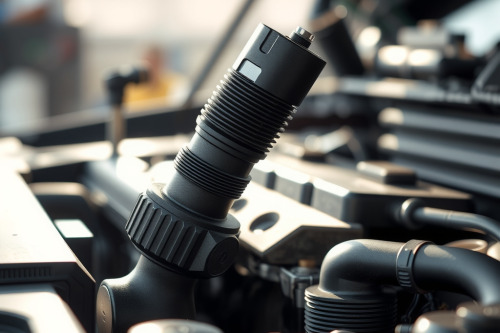
An illuminated check engine light triggered by a P0130 diagnostic trouble code indicates an open or unstable circuit in Bank 1 Sensor 1. In my years running diagnostic bays, ignoring this failure consistently leads to fouled spark plugs, unburned fuel entering the exhaust, and an overloaded catalytic converter. Replacing a faulty oxygen sensor is a routine mechanical task that restores stoichiometric balance before costly collateral damage occurs. With basic hand tools and disciplined safety measures, you can complete the repair in under 60 minutes.
Understanding the P0130 Code and Sensor Failures
The engine control unit (ECU) relies on the upstream oxygen sensor located ahead of the catalytic converter to regulate the air-fuel mixture. The P0130 code sets when the signal voltage stays between 0.40V and 0.55V for too long, or fails to cycle between 0.1V and 0.9V as engine load changes. The ECU stops closed-loop fuel monitoring and reverts to a rich default map.
A rich mixture drives fuel economy down by 10% to 15%. Raw hydrocarbons degrade the sensor element over time, while engine oil or silicone contamination creates thermal insulation over the ceramic tip. Bench testing with a reliable multimeter quickly identifies whether the sensor element is internally shorted or unresponsive to dynamic mixture swings.
Required Tools and Safety Protocols
Exhaust systems reach operating temperatures exceeding 400°C. Never attempt service on a hot vehicle; allow the engine bay to cool for at least 45 minutes before touching the exhaust manifold. Wear heavy nitrile gloves and wrap-around safety glasses to prevent rust scale and chemical penetrants from contacting your skin and eyes.
Tool List for the Job
- Dedicated 22mm (7/8-inch) slotted O2 sensor socket.
- 1/2-inch drive ratchet and a 250mm breaker bar.
- High-temperature penetrating oil (such as Kroil or PB Blaster).
- Wire brush for cleaning threaded bungs.
- Copper-based anti-seize paste (rated up to 980°C).
- OBD-II scanner capable of monitoring live fuel trim readings.
Locating the Upstream Oxygen Sensor
Identifying Bank 1 Sensor 1 is straightforward once you locate cylinder 1 on your engine block. On inline engines (4-cylinder or inline-6), all cylinders are on Bank 1, meaning Sensor 1 sits directly on the exhaust manifold before the primary converter. On V6 or V8 configurations, Bank 1 refers to the cylinder bank housing cylinder 1.
Sensor 1 is always the upstream sensor closest to the combustion chambers. Don't confuse it with Sensor 2, which sits downstream behind the catalytic converter and monitors catalyst storage efficiency rather than active combustion trims.
Step-by-Step Procedure for Replacing a Faulty Oxygen Sensor
Follow these steps methodically. Applying excessive force at the wrong angle risks stripping the bung threads out of the manifold casting.
Step 1: Prep and Penetrate the Threads
Soak the base of the threaded bung with penetrating oil while the exhaust pipe is lukewarm (around 30°C to 40°C). The slight thermal expansion allows fluid capillary action to pull the lubricant into rusted threads. Let it sit for 15 minutes.
Step 2: Disconnect the Electrical Connector
Trace the sensor pigtail up to the engine harness bracket. Press down firmly on the connector locking tab with your thumb or a flat pry pick. Pull the plastic bodies straight apart; never yank on the wires, or you will pull pins out of the vehicle-side harness connector.
Step 3: Extract the Old Sensor
Slip the slotted O2 sensor socket over the sensor body, sliding the harness through the side slot. Seat the socket squarely over the hex flats. Attach your breaker bar and apply steady, counterclockwise torque. If the sensor binds, rock the ratchet back and forth in 5-degree increments rather than snapping it loose with sudden impact.
Step 4: Prepare the Bung and Install
Clean the female threads in the manifold using a small wire brush to remove carbon and loose rust. Most replacement units come pre-coated with anti-seize on the threads; if yours didn't, apply a thin film around the midpoint of the threads. Keep anti-seize completely off the perforated sensor snout.
Thread the new sensor in by hand for at least 3 full turns to prevent cross-threading. Slide your socket over the body and torque the unit to factory specification, which is typically 40 Nm to 50 Nm. Reconnect the harness clip until you feel and hear a positive click.
Post-Installation Diagnostics and Verification
Clear the stored trouble codes using your scan tool before starting the engine. Start the motor and let it idle until coolant reaches normal operating range (roughly 85°C to 95°C). Switch your scanner to live data mode.
Observe short-term fuel trim (STFT) and upstream O2 sensor voltage. A healthy sensor will rapidly oscillate between 0.1V and 0.9V roughly 1 to 2 times per second at idle. STFT values should stabilize within a standard range of -5% to +5%. If voltage remains pinned at a static number, recheck your electrical harness pins for bent terminals.
Pragmatic Advice for Replacing a Faulty Oxygen Sensor
Always source direct-fit OEM sensors rather than universal splice-in alternatives. Universal sensors introduce resistance variations across crimp connectors, which alter delicate millivolt signals and lead to phantom diagnostic codes. Inspect the old sensor face: white powdery buildup points to coolant leaks, while thick black soot indicates persistent rich conditions that must be addressed separately. Clear your vehicle code now, verify your sensor cycling on live data, and take the car on a 15-minute drive cycle to make sure all emissions readiness monitors complete successfully.