
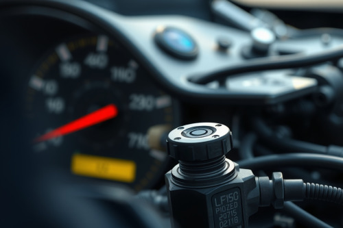
A triggered P0715 transmission input speed sensor code typically sends your automatic transmission straight into limp-home mode, locking the gear ratio in second or third. During bench diagnostics across dozens of late-model gearboxes, I've seen technicians replace functional sensors simply because they skipped basic waveform validation. Missing pulses instantly blind the powertrain computer, cutting calculated line pressure and wrecking shift timing. You must pinpoint whether the fault lies in the harness, pickup coil, or reluctor ring before buying hardware.
What triggers the P0715 transmission input speed sensor code
The transmission control module relies on steady electrical pulses to track turbine shaft velocity. This metric, combined with engine crank position data, dictates clutch pack application timing. The P0715 transmission input speed sensor code sets when the control module detects zero signal or erratic voltage fluctuations while the vehicle operates under load at speeds exceeding 25 km/h.
Two primary sensor designs dominate the field: variable reluctance and Hall effect. Variable reluctance sensors generate an alternating current voltage that climbs proportionally with shaft RPM. In contrast, Hall effect units use external reference voltage, toggling a clean 0V to 5V digital square wave. When the module observes a complete loss of turbine speed sensor circuit continuity for 2 consecutive drive cycles, it logs the diagnostic trouble code and restricts transmission operation.
Critical symptoms and real-world failure patterns
Ignoring this diagnostic fault damages internal friction clutches. The control module can't calculate slip ratios without accurate input shaft speed readings. So, the transmission adopts aggressive baseline hydraulic pressure to avoid burning clutch material.
Harsh engagement and fixed gear lock
Shift flares occur between 1st and 2nd gear, followed by sudden, violent shifts. If the signal drops out entirely, the module commands default third-gear operation. You will notice high engine RPM during highway driving, or sluggish off-the-line acceleration caused by stationary high-gear starts.
Erratic speedometer and erratic lockup
Torque converter clutch engagement becomes impossible without stable input data. The converter remains open, driving transmission fluid temperatures past 110 degrees Celsius under sustained highway loads. In dual-purpose systems, speedometer needles may bounce or drop entirely if the cluster calculates road speed from turbine-to-output ratios.
Electrical testing and bench data parameters
Never rely strictly on trouble codes. Pull out your diagnostic tools and run baseline electrical tests across the sensor connector terminals before removing any physical components.
Digital multimeter resistance test
For standard two-wire inductive sensors, isolate the sensor harness and perform a resistance measurement across the pins. A healthy coil reads between 800 ohms and 1400 ohms at 20 degrees Celsius. An infinite resistance reading confirms an internal open circuit, while anything below 400 ohms indicates an internal winding short. Discard two-wire sensors failing this benchmark immediately.
Signal verification using an instrument
Three-wire sensors can't be verified through resistance alone. Supply 12V or 5V power to the input pin, establish ground, and monitor the signal lead. Back-probe the connector and spin the target wheel by hand, or connect an oscilloscope to observe the trace. Look for consistent amplitude without missing peaks or voltage dropouts below 0.5V on the ground rail.
Step-by-step repair guide for P0715 transmission input speed sensor code faults
Methodical diagnosis prevents unnecessary parts replacement. Follow this exact technical sequence to isolate the failure point cleanly.
Step 1: Check live data stream
Connect a professional scan tool and select the live data menu inside the transmission module. Monitor turbine speed alongside engine RPM while the vehicle sits on a lift. Accelerate the powertrain to 1500 RPM in drive. If turbine speed registers 0 RPM while wheel speed rises, the sensor circuit is dead.
Step 2: Inspect wiring harness and connectors
Trace the harness from the sensor plug back to the transmission bulk connector. Transmission fluid migration frequently wicked up through old terminal pins, contaminating the connector shell. Clean oil soaked pins with contact cleaner. Measure wire continuity between the sensor pin and the module pin; resistance must stay below 0.8 ohms.
Step 3: Component replacement procedure
Drain transmission fluid if the sensor mounts internally inside the valve body casing. Remove the retaining bolt, usually an 8mm or 10mm fastener torqued to 10 Nm. Pry the old sensor straight out to prevent snapping the plastic nose inside the case. Coat the new O-ring with fresh automatic transmission fluid, torque the retaining bolt to 9.5 Nm, and reconnect the harness firmly.
Common diagnostic mistakes and reluctor ring verification
Replacing the sensor won't resolve a P0715 code if the mechanical target inside the transmission is damaged. Missing teeth on the reluctor ring produce intermittent signal dropouts that mimic wiring opens.
Insert an inspection camera through the sensor mounting hole. Rotate the transmission output shaft slowly while observing the teeth. Broken teeth, heavy metal shaving accumulation, or excessive axial endplay on the input shaft will disrupt the magnetic air gap. The clearance between sensor tip and tooth must measure between 0.5mm and 1.2mm. Any gap exceeding 1.5mm degrades signal amplitude below the detection threshold of the module.
Practical recommendations for resolving the code
Don't clear the P0715 transmission input speed sensor code until you have verified sensor supply voltage, chassis ground integrity, and harness continuity under load. Low transmission fluid levels do not directly generate this electrical fault, but excessive clutch debris in dirty oil regularly coats the magnetic pickup, attenuating the pulse amplitude. Flush contaminated fluid and address harness chafing near hot exhaust pipes. Once repairs are completed, clear the trouble codes, perform a transmission adaptive relearn procedure, and complete a 20-minute road test to make sure full operational readiness.