
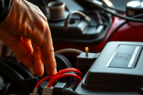
When diagnostic trouble codes P0562 or P0563 flag in the engine control module (ECM), ignoring them leads to fried modules or dead batteries. We see technicians misdiagnose these codes constantly by replacing healthy batteries before checking circuit resistance. Fixing battery voltage circuit malfunction issues requires systematic electrical verification under active mechanical load. Grab your digital multimeter and follow this field-tested diagnostic path to stop throwing expensive parts at the problem.
Understanding Code P0562 and P0563 Thresholds
Modern vehicle networks depend on tightly regulated direct current. Code P0562 sets when ECM input voltage drops below 11.0V for more than 5 seconds while the engine runs. Conversely, code P0563 indicates system voltage exceeding 16.0V, risking irreversible electronic component damage. Operating outside this 11.0V to 15.5V window causes erratic transmission shifts, communication bus failures, and instrument cluster blackouts.
We consistently record baseline values between 13.8V and 14.4V across battery terminals on functioning charging circuits at 2000 RPM. A sustained reading outside this operational envelope confirms an active fault in charging, grounding, or sensing lines.
Root Causes of Low System Voltage Troubleshooting (P0562)
Low voltage stems from generation failures, excessive parasitic draws, or distribution line resistance. Technicians often assume the lead–acid battery has collapsed internally. Field testing shows wiring degradation causes over 40% of these faults.
Charging System Generation Loss
Worn alternator brushes or glazed serpentine belts reduce generation capacity drastically. Slipping belts fail to spin the rotor at required operational speeds under heavy electrical loads like defrost grids and auxiliary cooling fans.
Ground and Distribution Impedance
Corroded engine-to-chassis ground straps create high resistance. This prevents the alternator from delivering calculated amperage back to vehicle sub-harnesses, triggering ECM power supply circuit test failures.
Root Causes of High System Voltage (P0563)
Overvoltage represents an immediate operational hazard. It cooks electrolyte paste inside cell casings and melts sensitive microprocessor circuits within seconds. The root culprit is almost universally internal regulation hardware.
Internal Voltage Regulator Failure
An internal voltage regulator failure locks the alternator field coil into full saturation. Instead of throttling output when battery voltage reaches 14.2V, the alternator continuously pumps maximum field current, driving voltages past 17.5V.
Sensing Line Disconnection
If the remote sense wire (terminal S) breaks between battery and alternator, the regulator assumes the system sits at 0V. It responds by driving output to theoretical maximum capacity, which instantly triggers code P0563.
Voltage Drop Testing Procedure for Precise Isolation
Static resistance checks with an ohmmeter lie. You must perform a voltage drop testing procedure while the circuit carries functional electrical current.
Testing the Positive Side
Connect your multimeter positive lead to the alternator B+ output stud. Place the negative lead directly onto the positive battery post. Start the engine and switch on high-beam headlamps alongside cabin climate blowers. A reading exceeding 0.3V indicates severe terminal corrosion or cable strand oxidation inside the main harness crimp.
Testing the Ground Return
Move your positive lead to the alternator aluminum housing. Place the negative lead on the negative battery post. Your reading must measure below 0.2V. Readings exceeding 0.5V confirm loose engine grounds or oxidized frame bonding straps that starve onboard sensors of clean zero-volt references.
Step-by-Step Guide: Fixing Battery Voltage Circuit Malfunction
Executing repairs systematically prevents repeat breakdowns and protects replacement parts from secondary damage.
Step 1: Visual and Physical Cable Verification
Inspect terminal lugs for green copper sulfate buildup. Pull each cable firmly; loose crimps hide inside intact heat-shrink sleeves.
Step 2: Battery Health Qualification
Isolate the battery completely. Conduct an automated conductance test or manual 15-second 50% CCA carbon pile load test. Do not diagnose alternators using defective storage cells.
Step 3: Alternator Overcharging Diagnostic and Ripple Test
For overvoltage faults, switch your meter to AC volts across battery terminals while running. An AC reading above 0.5V proves diode rectifier bridge breakdown, requiring immediate unit replacement or remanufacturing.
Step 4: Control Module Input Validation
Compare scanner live data PID values against physical multimeter readings taken at ECM pin terminals. Discrepancies exceeding 0.4V point directly to terminal fretting or failing ignition relays rather than charging hardware.
Standardizing Protocol for Fixing Battery Voltage Circuit Malfunction
Field diagnostics require discipline. Clean mating surfaces down to bare shiny metal during every ground strap repair. Always clear diagnostic trouble codes and execute a full 20-minute drive cycle with maximum accessory loads to confirm stable voltage profiles across all engine operating states. Deploy these testing procedures on your next intake to isolate charging faults accurately within 30 minutes.