
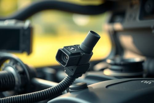
A sudden check engine light warning for knock sensor circuit low input compromises ignition timing and drops engine efficiency. In my years running diagnostic bays, ignored low-voltage signals frequently lead to heavy detonation under load. We must address this DTC before ECM failsafes pull boost and retard timing severely. Follow this guide to locate the root cause on your bench or lift.
Understanding Knock Sensor Circuit Low Input Faults
Modern powertrains rely on acoustic monitoring to prevent pre-ignition damage. The knock sensor functions via an internal piezoelectric element. This crystal converts mechanical vibrations from the engine block into an alternating current signal. Under normal operating conditions, the engine control module DTC logic monitors this continuous baseline chatter.
When the signal line drops below calibrated voltage thresholds (typically under 0.5V for more than 4 consecutive drive cycles), the computer flags P0327. This specific fault doesn't mean your engine is pinging. Rather, it indicates the control module can't hear the engine at all. The computer detects silence on the circuit and defaults to retarded timing maps to shield pistons from catastrophic damage.
Essential Equipment for Knock Sensor Circuit Low Input Testing
Don't throw new parts at this fault blindly. Successful troubleshooting requires basic testing instruments to eliminate harness breaks and shorted conductors. Bring these essential tools to your bay:
- An OBD2 diagnostic scanner capable of reading real-time sensor data and freeze frames.
- A quality digital multimeter with sharp back-probe pins.
- A calibrated 1/4-inch drive torque wrench reading in Newton-meters.
- A wire brush and contact cleaner for ground mating surfaces.
Isolating Wiring and Connector Failures
Visual Harness Inspection
Start with the sub-harness under the intake manifold. Rodents frequently nest in engine valleys and chew fragile signal lines. Look for brittle plastic shielding, burnt wire insulation resting on exhaust manifolds, and green corrosion inside weather-pack seals. Shake the harness while monitoring live scanner data to reveal intermittent breaks.
Voltage Drop and Continuity Checks
Disconnect the sensor and turn the ignition switch to the run position with the engine off. Set your meter to DC volts and measure the reference wire against chassis ground. Most vehicle platforms give a 2.5V or 5V bias signal from the module. If your reading stays at 0V, you've an open circuit or a signal wire shorted directly to chassis ground.
Check continuity on the ground return pin next. Resistance must stay below 0.2 ohms between the harness ground terminal and battery negative. Any higher resistance indicates corroded splices upstream.
Bench Testing and Sensor Installation Rules
Measuring Internal Resistance
Remove the component from the engine block for bench isolation. Connect your meter leads across the sensor terminal and the brass mounting sleeve for single-wire units, or across both pins for two-wire sensors. Standard resonant sensors show resistance values between 90k ohms and 600k ohms depending on OEM specifications. A reading showing 0 ohms indicates a fatal short, while an infinite reading indicates an internal break in the crystal stack.
Torque Calibration Requirements
Mechanical installation errors cause roughly 40% of false low-input codes. Knock sensors don't tolerate inaccurate tightening. Under-torquing isolates the sensor body from block resonance, producing voltage readings far below the required threshold. Over-torquing crushes the internal crystal, cracking the element and killing the return signal entirely.
Torque the mounting bolt strictly between 20Nm and 25Nm according to your factory service manual. Never apply thread locking compounds, anti-seize, or washers unless specified by the manufacturer. Clean the engine block mounting boss thoroughly until bare cast iron or aluminum is visible.
Resolving Knock Sensor Circuit Low Input Permanently
Field data proves that resolving this DTC requires verifying the entire signal path rather than swapping sensors repeatedly. Defective aftermarket components flood the market with out-of-spec resistance, so rely on OEM units whenever replacement is unavoidable. Secure the wiring loom away from secondary ignition cables to prevent inductive interference from masking normal baseline frequencies. Clear all trouble codes, perform a complete drive cycle under mixed load, and verify that baseline sensor voltage holds steady throughout the RPM band.