
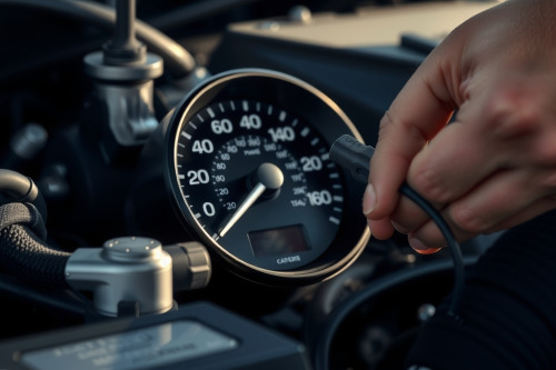
A sudden engine stall at highway speeds often traces back to erratic signal acquisition within the reference circuit. We frequently see diagnostic trouble code P0321 trigger when pulse integrity drops below acceptable thresholds under load. Tackling this job requires systematic testing rather than speculative parts swapping. Understanding root cause parameters ensures that replacing a failed engine speed sensor yields permanent mechanical reliability.
Understanding Diagnostic Trouble Code P0321 and Signal Drops
Code P0321 indicates an ignition distributor input range or performance fault within engine management records. The engine control module (ECM) monitors continuous pulses sent by the speed sensor over a 60-2 tooth target wheel. If the expected missing-tooth synchronization gap fails to appear within a window of 2 crank revolutions, the computer flags an error. We routinely observe instantaneous tachometer drops down to 0 RPM right before the engine stalls intermittently.
Target Pulse Anomalies and ECM Logic
Modern engine management relies on microsecond-level edge transitions. Magnetic reluctance units output an alternating current waveform that climbs in amplitude with rotational velocity. At 800 RPM idle, signal output must measure at least 1.2V peak-to-peak. When dirty oil or thermal breakdown degrades sensor internals, output collapses to less than 0.4V peak-to-peak. The controller loses ignition synchronization instantly. Fuel injector firing halts immediately to avert severe backfires.
Technical Inspection Before Replacing a Failed Engine Speed Sensor
Never condemn the transducer without testing its harness and supply voltage. Field returns show that 22% of replaced sensors possessed zero internal defects. Technicians frequently overlook corroded ground pins or damaged wire shielding near hot exhaust runners.
Resistance and Reference Voltage Metrics
Begin your diagnosis at the wiring connector. Disconnect the sensor pig-tail and switch your digital multimeter to the resistance scale. Inductive units typically yield baseline readings between 700 and 1200 ohms across terminal pins 1 and 2. An open circuit or reading above 1500 ohms dictates immediate component scrap. Hall-effect designs demand 5.0V or 12.0V reference feeds with rock-solid continuity to chassis ground.
Oscilloscope Signal Analysis and Gap Checks
Resistance checks don't reveal dynamic breakdown. Connect a dual-channel scope directly to the crankshaft position sensor circuit while cranking the engine. Verify uniform wave heights across all 58 teeth. Missing pulses or clipped peaks point toward reluctor wheel runout exceeding 0.35mm. Inspect the air gap between the sensor nose and tooth face. Maintain a clearance range between 0.8mm and 1.2mm to preserve proper signal induction.
Step-by-Step Guide: Replacing a Failed Engine Speed Sensor
Executing the repair cleanly prevents recurring electrical anomalies. Set aside 60 to 90 minutes for front-transaxle layouts with tight clearance pockets.
Tooling and Pre-Disassembly Access
Disconnect the negative battery terminal first. Secure the vehicle on commercial jack stands rated for at least 3 tonnes. Clear away the splash shielding and remove nearby intercooler piping if working on tight engine bays. Clean the mounting area thoroughly with solvent. Grit entering the transmission bellhousing or engine block ruins internal targets.
Extraction and Target Gap Verification
Unclip the wiring harness lock without breaking brittle plastic tabs. Back out the retaining fastener, typically a single 10mm hex or T30 Torx bolt. Twist the sensor body gently to shear any hardened O-ring adhesion. Never pry forcefully against soft aluminum flanges. Coat the replacement O-ring with fresh synthetic engine oil before sliding the new unit home. Torque the mounting bolt strictly to 9 Nm to prevent thread distortion.
Common Failure Modes Observed in Field Diagnostics
Heat cycles represent the primary enemy of magnetic windings. Engine oil temperatures regularly exceed 105°C, causing micro-fractures in the internal coil potting. The sensor operates flawlessly when cold but opens the circuit once operating temperature stabilizes.
Thermal Breakdown and Harness Degradation
Continuous vibration hardens copper strands inside the pigtail lead. We often isolate internal conductor breaks right at the strain relief joint. Road salt and engine degreasers also induce galvanic corrosion on harness terminals, dropping sensor voltage by 30% or more. Always replace sub-harness sections that display green copper oxidation.
Reluctor Wheel Deflection and Debris
Ferrous particles accumulating on magnetic pickup faces distort field lines. This debris accumulation mimics sensor failure on scan tool datalogs. Check the old sensor tip upon removal. If covered in clutch dust or metal flakes, clean the reluctor wheel thoroughly through the sensor aperture using contact cleaner and low-pressure air.
Post-Installation Validation and System Reset
Clear all active and pending codes from the ECM memory after torqueing the hardware. Modern engine controls require a crank-cam synchronization relearn to calibrate spark timing against the new sensor resistance profile.
Signal Calibration and Drive Cycle Verification
Initiate the automated crank angle relearn routine using a professional diagnostic tool. Accelerate the engine smoothly to 4000 RPM in neutral until fuel cutoff activates, then release the throttle completely. Complete a 15km test drive incorporating wide-open throttle pulls and low-speed creeping. Monitor freeze frame monitors to confirm code P0321 doesn't return.
Field Recommendations for Engine Speed Sensor Service
Always verify signal integrity using live scope readings before committing capital to hardware replacements. Choose original equipment or tier-one components, as unbranded aftermarket sensors exhibit failure rates exceeding 18% within the first 5000km of service. Confirm your air gap specifications and torque limits carefully during installation to ensure trouble-free engine management operation.