
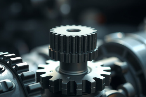
A transmission stuck in limp mode often triggers code P0730 during loaded acceleration tests. In our field diagnostic runs, a persistent gear ratio incorrect fault indicates mechanical slip rather than a trivial sensor glitch. Ignoring this warning destroys friction plates within 50 km of highway driving. You must analyze live telemetry before tearing down the casing.
Telemetry thresholds behind the gear ratio incorrect fault
The transmission control module logic monitors rotational dynamics continuously. It calculates the expected gear ratio by dividing input shaft speed by output shaft speed. If the calculated ratio deviates from the commanded gear ratio by more than 200 rpm for longer than 500 ms, the module flags code P0730. Modern units will command maximum line pressure immediately. This safety measure attempts to stop clutch pack slippage before metal-on-metal friction occurs.
You cannot rely solely on generic scan tool readings. Pull freeze-frame parameters immediately. Focus on commanded gear, actual input speed sensor values, engine load percentage, and throttle position. If input shaft speed flares during an upshift while output speed stagnates, mechanical engagement has failed.
Hydraulic verification and line pressure testing
Check the automatic transmission fluid level before mounting diagnostic equipment. Low fluid volume introduces air bubbles into the hydraulic passages. Aerated fluid compresses easily, causing severe clutch slippage. Pull the dipstick or access the overflow plug at 40°C fluid temperature. Burnt, dark fluid with friction material particulates confirms internal clutch degradation.
Line pressure tells the true story. Thread an analog 0 to 30 bar pressure gauge into the dedicated transmission main line tap. Run the engine through specific operational stages:
- Idle in Park: minimum 4 bar (58 psi) required across standard planetary units.
- Drive at Idle: pressure must remain between 4.2 bar and 5.5 bar.
- Stall Test: snap wide-open throttle in reverse and drive; pressure must spike rapidly to 14 bar (203 psi) or higher.
Pressures resting below 3.5 bar at idle point directly to a failing oil pump, blown pressure regulator valve bore, or clogged filter pickup screen. Insufficient clamping pressure allows clutch discs to spin against steel plates, generating code P0730 within seconds of high-load engagement.
Isolating shift solenoid valve failure and electro-hydraulic circuits
Hydraulic spool movement depends entirely on solenoid integrity. A shift solenoid valve failure starves clutch circuits of necessary fluid volume. Measure electrical resistance across all solenoid terminals at the transmission case pass-through connector. Standard linear solenoids read between 11 ohms and 15 ohms at 20°C, whereas pulse-width modulated solenoids generally register 3.5 ohms to 6 ohms.
Bench-test suspicious solenoids under air pressure. A solenoid can pass a static multimeter ohm check yet fail mechanically when warm. Heat cycles expand internal plunger sleeves, causing them to bind at operating temperatures above 85°C. When a solenoid sticks in the exhaust position, fluid dumps back into the oil pan instead of locking the clutch pack. Coupling issues inside the torque converter can also starve the input circuit, creating erratic hydraulic drops across the forward clutches.
Evaluating clutch pack wear and transmission slip rpm delta
Analyze live data logs on a level road test. Record the transmission slip rpm delta during 1-2, 2-3, and 3-4 gear shifts. Slip values must drop to zero within 250 ms to 400 ms of command initiation. If slip values exceed 180 rpm during steady cruise in 3rd or 4th gear, internal sealing rings or piston seals have failed.
Mechanical clearance benchmarks
Worn friction linings expand pack travel distance. Standard forward clutch clearance ranges between 0.8mm and 1.2mm. When friction material sheds, clearance easily exceeds 2.2mm. The hydraulic piston cannot stroke far enough to clamp the pack before the module detects a mismatch in shaft speeds, logging a gear ratio incorrect fault.
Root causes of a gear ratio incorrect fault across common platforms
Valves wear aluminum bores down over 150,000 km of service. Fluid bypasses the spool lands, depriving downstream clutches of targeted clamping force. Vacuum testing the valve body provides objective data:
- Sonnax vacuum test standard: minimum 18 in-Hg at critical regulator and boost circuits.
- Readings below 14 in-Hg: excessive bore wear requiring oversized reaming or complete casting replacement.
- Input and output speed sensor tone rings: inspect for cracked teeth or magnetic debris contamination, which generates corrupt frequency pulses.
Field protocol for resolving a gear ratio incorrect fault
Stop clearing the fault code repeatedly without mechanical intervention. Resetting the adaptive memory forces the transmission control module logic to relearn clutch fill volumes against worn friction plates, accelerating total mechanical failure. Perform a wet fluid inspection, conduct manual line pressure testing at operating temperature, and verify valve body vacuum integrity before ordering internal hard parts. Set up your pressure gauges and capture real telemetry on your scan tool today.