
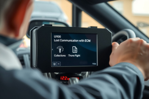
A sudden crank-no-start condition accompanied by a blank instrument cluster usually points straight to a network dropout. In my workshop experience, scanning multiple modules that all report no response from engine management confirms code U0100 lost communication with ECM. You can't fix this issue by throwing expensive modules at the vehicle before validating physical wiring. Grab your digital multimeter and follow this systematic approach to isolate the root cause on the shop floor.
Understanding Code U0100 Lost Communication with ECM Network Topology
Modern vehicles run high-speed Controller Area Network (CAN) lines operating at 500 kbps to link the powertrain with the rest of the chassis. Code U0100 sets when secondary modules, such as the Transmission Control Module (TCM) or Body Control Module (BCM), stop receiving periodic heartbeat messages from the ECM across this serial data bus. The failure may stem from total module power loss, internal transceiver breakdown, or physical data line damage.
A healthy network relies on two 120-ohm terminating resistors wired in parallel across the CAN High and CAN Low circuits. This configuration yields an overall reading of 60 ohms between pin 6 and pin 14 at the Data Link Connector (DLC). If one terminating resistor fails or wiring opens, the resistance changes to 120 ohms, corrupting data packets across the entire loop.
Preliminary Inspection and Battery Voltage Thresholds
Before pulling harness connectors, check baseline battery voltage under load. Low system voltage routinely shuts down digital communication chips inside the controller while starter motors still spin.
- Static voltage must read at least 12.4V across the terminals.
- Voltage drop during cranking mustn't drop below 9.6V for more than 250ms.
- Clean heavy corrosion off the engine ground straps and battery negative post.
Clean power is critical for automotive computing. Even minor transient spikes or dropped grounds make microprocessors reset repeatedly, logging false network faults.
Verifying Power Feeds and Grounds Before Condemning Hardware
Never condemn an engine controller until you prove it receives battery feed, ignition switch power, and ground under real electrical load. High-impedance digital meters display 12V through a single unbroken strand of copper wire, but that strand cannot deliver the 3A to 5A needed by internal circuitry.
Performing Loaded Voltage Drop Tests
Back-probe the main ground pins at the harness plug using an incandescent test light or a 4A headlamp bulb to put real current through the circuit. If the test lamp glows brightly and your meter shows less than 0.2V between the ECM ground pin and the negative battery post, the ground path is solid. Repeat this loaded check on constant unswitched battery pins and switched ignition feeds routed through the main system relay.
Inspecting the Main Powertrain Relay
A pitted relay contact drops internal voltage down to 8V when internal solenoids energize. Swap the engine control relay with an identical non-critical relay from the horn or rear defogger circuit to verify relay engagement during important-on sequence.
Isolating the Data Bus for Code U0100 Lost Communication with ECM
Disconnect the negative battery terminal and connect a breakout box to the DLC connector under the dashboard. Measure resistance between pin 6 (CAN High) and pin 14 (CAN Low). A display of 60 ohms indicates intact parallel termination, but this test does not reveal intermittent short circuits to chassis ground or battery voltage.
Voltage Bias Measurements
Reconnect the battery, turn the ignition important to the run position, and switch your meter to DC volts:
- CAN High (pin 6) should idle around 2.5V and pulse upward toward 3.5V during data transmission.
- CAN Low (pin 14) should idle around 2.5V and pulse downward toward 1.5V simultaneously.
- Sum of both lines must equal about 5.0V at any given microsecond.
If CAN High reads 12V, a harness short to a neighboring power wire has saturated the network. If either line sits at 0V, you face a dead short to sheet metal or a shorted transceiver diode inside an interconnected module.
Systematic Module Unplugging
If bus voltages remain skewed, disconnect modules one by one while monitoring line voltage on the DLC breakout box. Unplug the anti-lock brake module first, followed by the electronic power steering unit and transmission module. When line voltages snap back to normal 2.5V bias, the module you just disconnected contains the internal circuit fault pulling down the bus.
Harness Integrity and Terminal Fretting Inspection
Intermittent network dropouts frequently trace back to fretting corrosion or bent female pins inside bulkheads rather than cut wires. Vibration over 80000 km erodes microscopic tin plating on terminal contacts, generating electrical resistance that garbles high-frequency CAN messages.
Use an appropriate male terminal probe to check pin drag on the main harness connector. If the test pin slides in and out without noticeable friction, the female terminal has lost its mechanical tension. Extract the pin, reform the retention spring with a pick, or splice in an OEM repair pigtail to establish firm mechanical contact.
Field Recovery Protocol for Code U0100 Lost Communication with ECM
Fixing code U0100 lost communication with ECM requires methodical elimination of power loss, bus shorts, and terminal damage before buying replacement computers. Test circuit voltage drops under working current rather than relying on unloaded multimeter checks. If you've confirmed clean 12V supplies, solid chassis grounds below 0.2V drop, and proper 60-ohm bus continuity directly at the module pins, replace the damaged engine controller and flash the latest calibrations using a J2534 pass-thru device.