
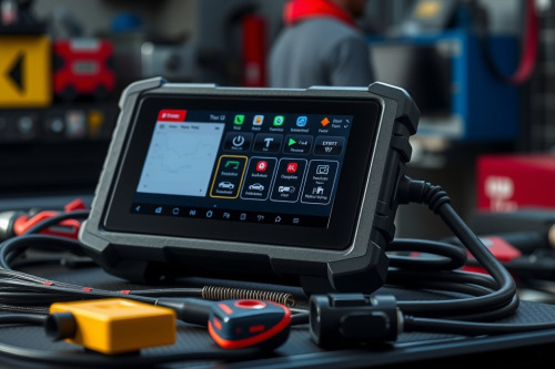
Budget handheld readers pull generic DTCs, but they leave technicians guessing when a multiplex network crashes under load. In my 14 years running shop diagnostics, nothing burns bay hours faster than swapping good sensors because an entry-level tool misread CAN bus packet loss. A true professional OBD2 diagnostic scanner changes the equation by interfacing with proprietary controller layers and running real-time actuation routines. Without these capabilities, your diagnostic path remains pure guesswork.
What a professional OBD2 diagnostic scanner accesses beyond emissions
Standard retail tools operate strictly within the bounds of SAE J1979 regulations. This limits your diagnostic scope to generic Mode $01 through Mode $0A data sets, covering basic tailpipe emissions mandates. If an engine misfire occurs, a basic reader outputs a simple P0300 code without providing secondary context.
Professional units bypass these generic gateways. They establish direct sessions with manufacturer-specific communication trees, querying proprietary controller networks directly. You gain full visibility into body control modules, ABS pumps, radar modules, and transmission control units. Instead of viewing 20 generic PIDs at a laggy 2Hz refresh rate, you capture hundreds of proprietary parameters at 50Hz over high-speed networks.
Bidirectional control versus passive code reading
Reading error codes represents only half of the diagnostic equation. When a cooling fan fails to engage, a passive code reader tells you that the coolant temperature exceeds standard limits. It cannot determine whether the fault lies in the relay, the wiring harness, or the engine control unit.
Active testing isolates mechanical failures from electrical circuit faults instantly. We use bidirectional controls to send forced actuation commands straight to the target component. You can command an ABS pump motor to cycle, trigger a variable valve timing oil control valve, or force open an EVAP vent solenoid to observe pressure drop on a fuel tank transducer. If the component actuates upon direct command, the circuit and driver stage work properly. This test cuts your diagnostic time from 2 hours down to 10 minutes.
Network topology mapping and high-speed CAN bus diagnostics
Modern vehicles run up to 70 separate microcontrollers linked across multiple data buses. Diagnosing communication faults with a basic code reader is impossible when a single malfunctioning module pulls down the entire circuit.
Visual topology mapping
High-end diagnostic platforms generate a real-time visual bus tree showing CAN High, CAN Low, LIN, and FlexRay networks. Modules render in green when operating normally, yellow when storing trouble codes, and red when unresponsive. You see communication line breaks immediately without disassembling interior trim panels.
Physical layer network testing
When an entire bus network drops offline, a professional platform isolates whether the line suffers from a short to ground, short to battery voltage, or a missing termination resistor. A normal high-speed CAN bus requires 60 ohms total loop resistance across its dual 120 ohm resistors. Premium diagnostic scanners monitor operating bus voltage in real time, alerting you when line voltage deviates from the standard 2.5V baseline.
Advanced ECU coding capabilities on modern vehicle platforms
Replacing a module on any vehicle built after 2015 requires software configuration before the unit functions. Basic scanners can't write data to vehicle memories. They read parameters, clear codes, and nothing more.
Workshop platforms support variant coding, parameterization, and J2534 passthrough programming. When you install a replacement steering angle sensor, you must zero out the calibration table inside the chassis controller. Replacing common rail diesel injectors requires inputting specific 16-digit IMA classification codes directly into the engine control unit. Professional platforms execute these routines through guided software sequences, eliminating costly trips to the dealership.
Hardware architecture inside a professional OBD2 diagnostic scanner
Consumer dongles rely on cheap microcontrollers that choke on complex data packets. Professional shop units run high-grade hardware architectures designed to withstand daily shop floor punishment.
- Processor array: Dedicated multi-core application processors paired with FPGA coprocessors handle vehicle communication protocols without dropping data frames.
- Input circuit protection: Vehicle electrical systems spike violently during starter engagement. Professional interfaces feature overvoltage protection up to 30V and maintain diagnostic sessions even when system voltage drops down to 8V.
- Screen and casing: Diagnostic bays expose equipment to oil, brake cleaner, and concrete drops. Professional platforms use capacitive touchscreens bonded to chemically hardened glass and carry IP65 drop-tested housings.
Field deployment criteria for workshop diagnostics
Selecting diagnostic gear requires matching tool capabilities to your specific bay repair profile. Don't buy a high-end tool merely for its brand name; inspect its protocol compatibility list carefully. Verify native support for CAN FD and DoIP protocols, which are mandatory for diagnosing modern chassis platforms.
Demand active subscription transparency from your equipment vendor. Certain tool brands lock all device operations when the update license expires, turning the unit into an expensive paperweight. Choose hardware that retains full offline functionality for existing software levels even if updates pause. Inspect your shop workflow, retire your generic handheld readers, and equip your bay with a capable professional OBD2 diagnostic scanner today.