
Automotive air conditioning failures usually strike during peak ambient heat, exposing weak components under heavy thermal load. Over 15 years in vehicle bay diagnostics taught me that guessing component failure wastes billable hours and damages compressors. This technical guide answers critical questions on how to diagnose car ac problems with systematic field methods. Grab your manifold set and electrical probe to isolate the exact fault before purchasing replacement parts.
Why is the car ac blowing warm air at idle?
Static air conditioning failure during idling points to insufficient airflow over the condenser or low refrigerant velocity. When the vehicle stops moving, ram air drops to 0 km/h. The radiator cooling fan must pull sufficient cubic feet per minute across the condenser coils to drop high-side pressure.
Check the cooling fan assembly immediately. A fan spinning below 1200 RPM under AC demand fails to liquefy high-pressure vapor. High-side pressures rapidly spike past 28 bar, triggering the high-pressure safety cutout switch to disengage the compressor clutch. Once the vehicle accelerates, natural airflow cools the condenser, pressures drop, and cooling resumes temporarily.
Another common cause is an internally worn compressor. At 800 engine RPM, a worn swash plate or leaking internal reed valve cannot generate the displacement needed to compress R134a or R1234yf refrigerant efficiently. If engine revs of 2000 RPM instantly drop vent temperatures by 8°C, suspect internal mechanical wear.
How to diagnose car ac problems using manifold gauge set readings?
Attaching pressure gauges to service ports provides direct insight into the refrigeration cycle. Connect the blue low-side coupler to the larger suction line port and the red high-side coupler to the smaller discharge line port. Stabilize the vehicle at 1500 RPM with doors open and blower fan on maximum.
Interpreting standard pressure benchmarks
At an ambient temperature of 30°C, baseline low-side pressure should sit between 2.0 bar and 2.4 bar (30 psi to 35 psi). Normal high-side pressure runs between 12 bar and 15 bar (175 psi to 220 psi). Significant deviations reveal specific mechanical bottlenecks inside the sealed circuit.
Recognizing circuit restrictions
A low-side reading pulling into a vacuum alongside standard or lower-than-normal high-side pressure indicates a severe blockage. Debris from a disintegrating desiccant bag typically plugs the thermal expansion valve orifice. Frost forming on the valve inlet confirms this restriction, as refrigerant expands prematurely before entering the evaporator core.
Conversely, equal pressures on both sides (e.g., both reading 5.5 bar with the engine running) show total compressor inaction. The compressor is either mechanically broken, de-stroked, or the clutch drive plate isn't engaged.
How to diagnose car ac problems tied to compressor clutch failure?
An automotive air conditioning compressor won't pump refrigerant if the magnetic clutch fails to lock the pulley to the main shaft. When the dash AC switch illuminates, visual inspection must confirm that the front clutch hub rotates at the same speed as the serpentine belt pulley.
Testing clutch coil resistance
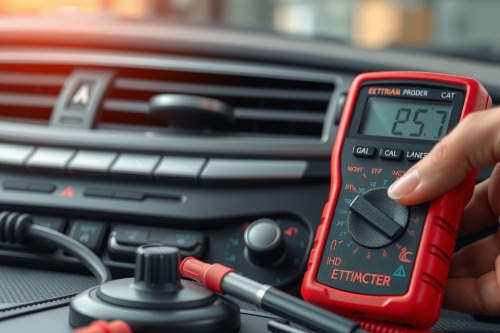
Disconnect the single-wire or two-wire harness at the compressor body. Measure coil resistance with a digital multimeter set to ohms. A functional 12V electromagnetic coil displays between 3.0 ohms and 4.5 ohms. A reading showing 0 ohms indicates a shorted coil, while infinite resistance indicates an open internal thermal fuse.
Measuring clutch air gap
Physical wear on friction plates increases the mechanical clearance over time. Insert feeler gauges between the driven plate and the pulley face. Factory clearance spans 0.35mm to 0.65mm. When wear expands this gap beyond 0.80mm, magnetic field strength can't pull the plate inward against spring tension, resulting in intermittent cooling loss under elevated engine bay temperatures.
What are the most reliable methods for refrigerant leak detection?
Refrigerant loss remains the primary root cause of mobile climate control failures. Never recharge an empty system without verifying structural integrity, as venting fluorinated gases breaches environmental regulations and wastes inventory.
Electronic sniffing and ultrasonic detection
Sweep an electronic heated-diode or infrared leak detector around high-risk failure zones at a travel rate of 25mm per second. Prioritize compressor shaft seals, crimped rubber hose junctions, and service valve Schrader cores. Electronic sniffers detect micro-leaks down to 3 grams per year, alerting you with audible frequency changes.
UV dye and nitrogen pressure testing
Inspect the lines using a 395nm ultraviolet light. Yellow-green fluorescent dye pooling beneath the condenser corner or around line O-rings pinpoints mechanical joint failure. For completely depressurized systems, charge the lines with dry nitrogen to 10 bar (145 psi). Apply soapy bubble solution to mechanical joints and monitor the manifold gauge for 30 minutes; needle drops confirm structural integrity loss before you charge costly refrigerant.
How do you distinguish between electrical faults and blend door malfunctions?
Technicians frequently misdiagnose HVAC control issues as mechanical refrigeration failures. If manifold gauge pressures meet factory specifications yet cabin air registers 24°C, inspect interior distribution controls.
Touch both aluminum AC lines passing through the bulkhead into the cabin. The low-pressure suction tube must feel cold and display condensation. The high-pressure liquid line must feel warm to the touch. If both lines exhibit correct thermal differential, the under-hood refrigeration loop functions as designed.
Shift diagnostic focus to the dashboard blend door actuator. An actuator motor with stripped nylon gears fails to pivot the internal flapper door, blowing heated air from the heater core directly across the cold evaporator. Connect an OBD2 scan tool capable of reading body control modules to recalibrate sweep angles and check for stored HVAC actuator position codes.
Final field checklist: how to diagnose car ac problems accurately
Accurate car air conditioning troubleshooting requires disciplined execution without skipping diagnostic milestones. Always check belt tension, confirm 12.6V supply voltage across the pressure transducer, and verify clean cabin air filter flow before condemning expensive components.
Procure recovery stations, vacuum pumps pulling to 500 microns, and calibrated electronic scales to manage charges within 15 grams of vehicle plate specifications. Apply these methodical procedures on your vehicle rack today to diagnose car ac problems efficiently and ensure reliable cabin cooling on the first attempt.