
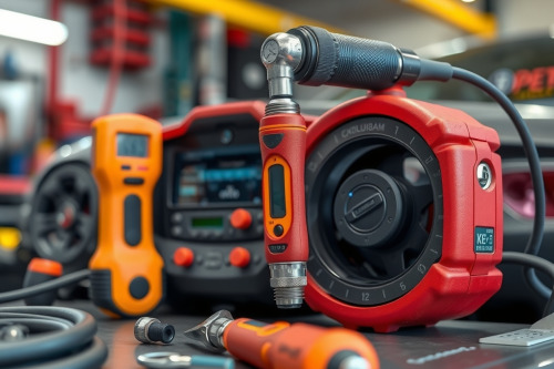
Throwing replacement parts at an unverified failure code wastes budget and leaves underlying mechanical faults unresolved. In my 15 years running diagnostic bays, systematic testing always outperforms raw guesswork. You must learn how to diagnose common car problems by measuring baseline sensor values and hydraulic pressures directly. This methodical workflow prevents catastrophic roadside breakdowns before components suffer secondary fatigue.
Triage Starting and Charging Systems to Diagnose Common Car Problems
Battery and Starter Current Draw
Verify static battery voltage across the lead terminals before inspecting any other sub-assembly. A fully saturated lead-acid battery reads 12.6V at rest, whereas 12.2V indicates a 50% state of charge. When cranking the engine, terminal potential must never plummet below 9.6V at 20°C ambient temperature. Excessive voltage drop highlights worn armature bushings, oxidized ground cables, or dead internal cells.
Isolate intermittent car starting issues by performing a dedicated voltage drop test across the main starter cable. Connect a digital multimeter between the battery positive post and the starter solenoid lug. Crank the engine for 3 seconds. Any measurement exceeding 0.2V reveals severe line resistance that starves the starter of amperage. Systematic automotive electrical troubleshooting relies on measuring circuit drops rather than checking basic continuity.
Alternator Output and Ripple Voltage
Start the motor and switch on all accessories to stress the charging system. Normal alternator output registers between 13.8V and 14.4V across the battery terminals. Switch your meter to AC millivolts to detect failing internal rectifier diodes. A healthy charging system limits AC ripple to less than 0.05V AC. If ripple spikes above 0.1V AC, replace the rectifier bridge immediately to prevent sensitive microcontrollers from crashing.
How to Diagnose Common Car Problems in the Ignition and Fuel Loop
Evaluating Ignition Coils and Spark Health
Pull spark plugs to inspect ceramic insulators and ground electrode wear when you encounter erratic engine misfire symptoms. Center electrode gaps should match manufacturer parameters exactly, typically between 0.7mm and 1.1mm. Measure primary coil resistance across terminal pins; expect readings between 0.5 and 1.5 ohms on modern coil-on-plug systems. Secondary resistance through the boot terminal should settle reliably between 6,000 and 12,000 ohms.
Swap suspected coils between cylinders to observe whether the misfire shifts position. If cylinder 2 logs a misfire, move that coil to cylinder 4 and retest under load. If the code shifts to cylinder 4, the ignition coil failed internally under high thermal load. If the fault remains at cylinder 2, direct your attention to fuel injection or compression issues.
Fuel Delivery and Injector Pulse Width
Connect a mechanical pressure gauge to the fuel rail Schrader valve before ordering new injectors. Port fuel injection engines require steady pressure around 3.5 bar, while direct injection rails demand upwards of 120 bar under load. Residual rail pressure must hold steady for at least 15 minutes after shutting the ignition off. A sudden pressure drop indicates a ruptured fuel pressure regulator diaphragm or a leaking pintle seat.
Scan Tool Protocol to Read OBD2 Trouble Codes
Interpreting Freeze Frame Data
Technicians must read OBD2 trouble codes alongside associated freeze frame snapshots to isolate the exact vehicle state during failure. Freeze frame data captures engine RPM, absolute manifold pressure, vehicle speed, and loop status the millisecond the fault occurred. Lean codes triggered strictly at idle point toward intake manifold gasket leaks or unmetered vacuum leaks. Lean codes triggered under wide-open throttle point toward clogged fuel filters or dying supply pumps.
Live Sensor Parameter Comparison
Monitor short-term and long-term fuel trim values simultaneously on your live data scanner. Healthy fuel management maintains total trim values within a tight band of +/-5%. Trim values exceeding +15% prove the engine control module is injecting supplemental fuel to compensate for unmetered air. Check your upstream oxygen sensor response speeds. A healthy switching zirconia sensor oscillates between 0.1V and 0.9V at least 3 times every 2 seconds at 2,500 RPM.
Hydraulic and Mechanical Brake Evaluation
Executing Spongy Brake Pedal Diagnosis
System air entrapment and fluid boiling cause noticeable compliance in pedal travel. Carry out a spongy brake pedal diagnosis by clamping hydraulic flexible hoses with dedicated hose pinchers. Clamp all 4 corners and apply firm foot pressure to the brake pedal. If the pedal is rock hard, the master cylinder is sound and air remains trapped in a caliper line. Release calipers one by one to isolate the specific hydraulic circuit housing moisture or trapped air.
Caliper Slide Pin and Rotor Runout Verification
Mount a dial indicator to the steering knuckle to verify brake rotor runout. Rotate the hub 360 degrees by hand while reading the gauge stylus against the friction ring. Maximum allowable lateral runout can't exceed 0.05mm. Excessive runout causes severe steering wheel oscillation under high-speed deceleration. Inspect caliper slide pins for corrosion and clean out dried lubricant using wire brushes before reassembling the carrier brackets.
Cooling Circuit and Thermal Management Failures
Pressure Testing Radiator Caps and Cores
Cooling system leaks starve the water jacket and cause rapid head warping. Fit a cooling system pressure tester to the radiator filler neck and pump the circuit to 1.1 bar. The circuit should hold target pressure for 10 minutes without dropping more than 0.1 bar. Check around the thermostat housing, radiator end tanks, and heater core bypass pipes for crusty coolant dye residues.
Thermostat Cycling and Water Pump Cavitation
Point an infrared thermometer at the upper and lower radiator hoses during warm-up cycles. The upper hose warms up first, while the lower hose stays cool until the thermostat cracks open around 88°C. A standard operating temperature gradient demonstrates a delta of 10°C to 15°C across the radiator core. A lower hose that remains cold despite engine temperatures exceeding 100°C indicates a stuck-closed thermostat or damaged water pump impeller vanes.
Practical Action Plan to Diagnose Common Car Problems
Never replace sensors or hydraulic components until mechanical integrity and circuit grounds pass manual inspection. Keep your scan tool updated, calibrate pressure gauges quarterly, and always verify battery health before hunting electrical phantoms. Work from physical symptoms down to electrical inputs systematically. Secure your diagnostic test leads, connect your scan tool to the data port, and verify baseline operating parameters before ordering your next replacement component.