
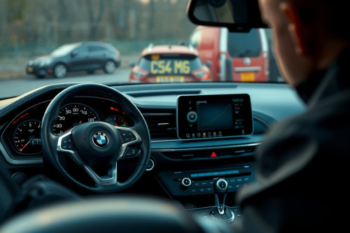
Modern engine bays turn into money pits when technicians fire the parts cannon at intermittent electrical faults. Over my 20 years busting knuckles in dealership and independent bays, I've watched bad grounds mimic failed controllers repeatedly. You must follow a disciplined strategy to diagnose sensor problems in modern cars before ordering expensive modules. Master this bench-tested sequence to protect your billable hours and fix cars right the first time.
Fundamental baseline to diagnose sensor problems in modern cars
Never trust a diagnostic trouble code at face value. A code for circuit low doesn't mean the sensor died on the highway. High electrical resistance on a ground wire produces the exact same code on your OBD2 scanner. Every working sensor circuit relies on three pillars: a clean power feed, a rock-solid return ground, and a reliable signal wire.
Check the battery terminals and main harness bonding straps first. Modern engine control units (ECUs) calculate calculations on microvolt fluctuations. A dirty battery terminal drops circuit voltage across the vehicle harness by 400mV to 800mV easily. That minor drop creates phantom glitches across multiple sensors sharing the same internal reference circuit.
Scan tool live data verification vs component failure
Roll your diagnostic workstation up to the fender and plug in your diagnostic platform. Don't jump straight to the parts catalog when chasing ghost trouble codes. Compare your live sensor data PIDs against known good values while the engine operates in closed-loop mode.
Analyzing plausibility across redundant inputs
Modern powertrain systems use redundant sensors to cross-check operational safety. An electronic throttle body monitors two integrated tracking channels simultaneously. One sensor tracks upward from 0.5V to 4.5V, while the second tracks inversely from 4.5V to 0.5V. When the sum fails to calculate exactly 5.0V, the powertrain module trips limp-home mode. Watch both data lines side-by-side to catch non-linear discrepancies during pedal sweep tests.
Catching frozen data frames
A frozen sensor reading indicates an open harness circuit or an internal calculation default. If an intake air temperature reading defaults permanently to -40°C, the signal line is completely broken open. An ECU seeing an infinite open circuit will drop its calculation to the bottom of the scale. Conversely, an ECU reporting 150°C indicates a direct short circuit to ground on that specific signal wire.
Harness inspection and reference voltage circuit testing
Pull your digital multimeter off your rolling cart before unbolting components. Modern sensor circuits predominantly operate on an isolated 5V reference supply generated internally by the engine computer. If that 5V bus collapses, every sensor running on that common circuit stops reporting accurate data.
Back-probe the reference pin at the harness connector with your meter negative clamp anchored directly to the battery negative post. A healthy circuit must read between 4.95V and 5.05V consistently. If your reading drops to 3.2V, pull sensor connectors off the 5V line one by one. Once you disconnect a shorted potentiometer or pressure transducer, the line voltage jumps back up to 5.0V instantly. That proves the harness is clean and isolates the specific defective component in minutes.
Dynamic signal validation with lab scope waveform analysis
Digital multimeters display an average voltage reading calculated across several milliseconds. That sampling rate is too slow to catch intermittent dropouts on high-speed components. Relying on an automotive oscilloscope waveform analysis allows you to observe high-frequency events in real time without guesswork.
Crankshaft and camshaft position sensor glitches
Variable reluctance and digital pick-up units generate fast switching pulses critical for ignition timing. Connect your scope leads to both the crank and cam circuits simultaneously. Look for missing trigger teeth or rounded edges on square wave patterns. A fluctuating 12V supply wire will degrade the amplitude of the signal, causing erratic misfires under wide-open throttle acceleration. A meter shows normal average voltage here, but the lab scope screen exposes the missing clock cycles immediately.
Oxygen and air-fuel ratio sensor response rates
Upstream wideband sensors manage modern air-fuel trims within razor-thin tolerances. Force a transient lean condition by pulling a vacuum line, then monitor signal reactivity on your scope display. The waveform must plunge below 200mV within 100 milliseconds. Sluggish transitions past 300 milliseconds confirm soot contamination across the sensing element, signaling imminent component replacement.
Systematic workflow to diagnose sensor problems in modern cars
Chasing electrical faults requires strict physical discipline to avoid falling into a costly diagnostic rabbit hole. Use this sequential checklist on every suspected sensor failure:
- Verify customer complaints and record all active freeze-frame parameters.
- Clear codes and perform a controlled test drive to verify repeatability.
- Measure power feed, reference voltage, and ground drop under active operating load.
- Perform dynamic wiggle tests on harness branch connectors while watching live scope captures.
- Inspect sensor harness shields for oil intrusion, corrosion, or physical abrasion against chassis brackets.
Adhering strictly to these bench steps eliminates guesswork. Every seasoned flat-rate tech knows that structured checks save countless hours of wasted bay time.
Final road test protocols for preventing comebacks
Replacing a bad sensor is only half the battle. You must clear adaptive fuel and timing maps stored inside the powertrain computer memory. The vehicle computer adjusted long-term fuel trim tables to compensate for the damaged component over thousands of miles. Forcing the vehicle to relearn baselines immediately prevents erratic idle and catalytic converter codes during customer delivery.
Run the vehicle through its full OEM drive-cycle monitors until the OBD2 scanner confirms all readiness flags report complete. Road test the car under the precise engine speed and load conditions captured in your initial freeze-frame data. Following this rigorous pathway to diagnose sensor problems in modern cars ensures accurate fixes every single time. Take your scope out, verify your reference circuits, and start testing instead of guessing today.