
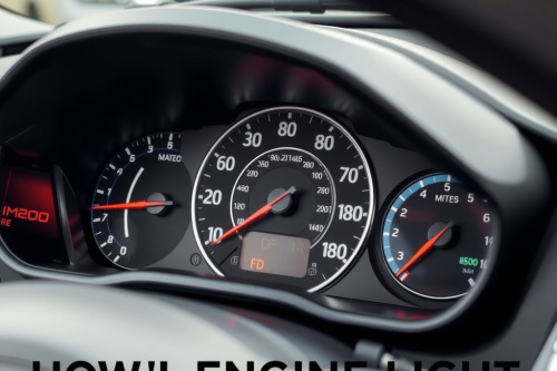
A glowing amber lamp on your cluster points directly to an unmetered air leak, combustion failure, or emissions threshold breach. In my 15 years running bay diagnostics, ignoring this indicator always cascades into melted exhaust hardware and tripled repair bills. Understanding how to fix a check engine light requires methodical troubleshooting rather than blindly throwing parts at the engine bay. Follow our bench-tested workflow to isolate the root failure and clear the code permanently.
Categorizing the Fault: Solid Versus Flashing Warning
Stop driving immediately if the dashboard amber icon blinks repeatedly. A blinking light signals severe cylinder misfires dumping unburned fuel directly into the exhaust stream. This raw fuel superheats the catalytic converter beyond 850°C, melting internal ceramic substrates within 5 minutes. Conduct a flashing check engine light diagnosis right away to identify dead ignition coils or stuck-open injectors before running the motor again.
A steady light presents less immediate mechanical danger. You can safely pilot the vehicle back to your workspace for evaluation. The onboard computer detected an out-of-range sensor voltage or an emissions check failure over two consecutive drive cycles. Keep engine load moderate. Avoid heavy towing or high-RPM acceleration until you establish the cause.
Diagnostic Equipment Setup to Read Diagnostic Trouble Codes
Never disconnect the 12V battery terminal to reset the system. Erasing the keep-alive memory clears critical freeze-frame records and forces you to restart diagnostic routines from scratch. Connect a dedicated handheld scan tool to the 16-pin data link connector beneath the driver dashboard.
Switch the ignition important to position 2 without cranking the starter. Command your device to read diagnostic trouble codes stored inside the engine control module. Write down both active and pending codes. Codes prefixed with P0 are standardized SAE faults, while P1 codes denote manufacturer-specific logic. Freeze-frame metrics show engine temperature, vehicle speed, and calculated load precisely when the diagnostic trip occurred.
Interpreting Real-Time Data Streams
Static DTC numbers only reveal where the system caught the deviation, not which component failed. Use OBD2 scanner live data to observe short-term fuel trim (STFT) and long-term fuel trim (LTFT) across both engine banks. Combined fuel trim values exceeding 10% indicate a lean state, frequently caused by vacuum leaks or failing fuel pumps. Negative trims past -10% demonstrate rich conditions from dripping injectors or restricted air intakes.
How to Fix a Check Engine Light Caused by Fuel and Air Leaks
Evaporative system codes P0440 through P0456 are common service triggers. Inspect the fuel filler neck for debris and examine the rubber gasket on your gas cap. A cracked 2mm seal allows fuel vapor escape, tripping an evaporative emission control leak code during engine vacuum testing.
Replace any brittle rubber hoses around the intake manifold and purge valve assembly. We locate micro-cracks by injecting low-pressure mineral smoke at 0.5 psi into the brake booster vacuum line. Leaking smoke pinpoints deteriorating intake gaskets or cracked plastic PCV pipes instantly. Tighten loose hose clamps to 3 Nm torque. Replace split vacuum lines with heat-resistant silicone hoses to prevent recurrent diagnostic warnings.
Sensor Triage and Faulty Oxygen Sensor Replacement
Heated oxygen sensors operating downstream and upstream degrade gradually after 100,000 km of service. Upstream sensors must oscillate rapidly between 0.1V and 0.9V at closed-loop idle. A sluggish sensor holding steady at 0.45V triggers lean or slow-response codes. Confirm circuit wiring before condemning hardware. Rodents chew wiring harnesses near the bellhousing, mimicking bad sensor elements.
If sensor performance graphs flatline on your screen, proceed with faulty oxygen sensor replacement using a 22mm slotted sensor socket. Apply penetrating solvent to the threads while the exhaust pipe remains warm to the touch. Thread the replacement sensor by hand to eliminate cross-threading risks. Torque the unit precisely to 42 Nm. Reconnect the automotive harness firmly, listening for the locking tab to click securely into place.
How to Fix a Check Engine Light Drive-Cycle Verification
Clear active DTC memory once your physical repairs are complete. Erasing DTCs automatically switches all system emissions monitors to "Not Ready" status. Taking the vehicle directly to an inspection station results in an immediate administrative rejection. You must execute an OBD2 drive cycle to confirm the fix.
Drive the vehicle steadily at 90 km/h for 15 minutes with fuel tank capacity between 25% and 75%. Decelerate to 35 km/h without touching the brake pedal to evaluate the purge solenoid operation. Idle the engine in drive for 3 minutes to verify catalytic efficiency metrics. Reconnect your scanner to make sure all monitors report "Ready" without setting pending trouble codes.
Systematic Bay Procedures and Final Recommendations
Mastering how to fix a check engine light saves thousands in speculative part replacements. Always verify mechanical base conditions before electrical troubleshooting. Verify that engine oil meets correct viscosity specifications, check engine grounds for zero ohm resistance, and verify steady fuel rail pressure. Pick up a capable diagnostic tool, pull your stored freeze-frame records, and methodically tackle the verified failure point today.