
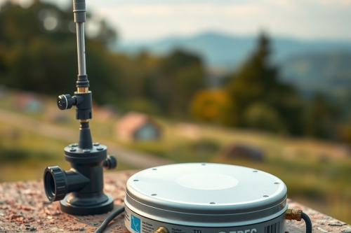
Weak satellite reception drops telemetry data and ruins navigation accuracy on commercial setups. In my field audits across fleet tracking and remote monitoring stations, poor placement consistently destroys receiver performance. You'll solve persistent tracking dropouts by installing external GPS antennas for better signals across your fleet or field equipment. Follow this hardware workflow to lock in dependable satellite fixes immediately.
Site Assessment Before Installing External GPS Antennas for Better Signals
GPS signals transmit from medium Earth orbit at 1575.42 MHz with extremely low power levels around -130 dBm. Any structural barrier between the sky and your receiver causes immediate signal degradation. You must guarantee an unobstructed 360-degree clear view of the sky down to 10 degrees above the horizon. Solid steel plates, tinted glass containing metal oxides, and concrete structures block satellite lines completely.
Maintain clean separation from high-frequency transmitters. Mounting hardware within 500mm of VHF, cellular, or radar transmitters introduces heavy RF interference into your receiver front end. We routinely measure 12 dB to 18 dB carrier-to-noise ratio drops when installers bundle GPS coaxial leads alongside high-current alternator wiring. Identify an elevated, flat mounting location that preserves an open line of sight to satellites before drilling mounting holes or running lead wires.
Required Hardware and Tools for Field Deployment
Field installations demand hardware built to endure moisture, vibration, and thermal cycling. Standard plastic consumer enclosures crack under sustained ultraviolet exposure within 12 months. Specify an IP67 or IP69K waterproof housing equipped with internal gaskets to prevent moisture ingress at terminal connections.
- Active GPS antenna with an integrated low-noise amplifier (28 dB gain standard)
- Low-loss 50 ohm coaxial cabling such as RG-58 or LMR-195
- Torque-rated spanners for threaded brass connectors
- Self-amalgamating silicone tape for weatherproofing external joints
- Multimeter for checking 3.3V or 5V DC phantom bias voltage
Make sure that your hardware selection accounts for specific ground plane requirements. Most ceramic patch antenna elements depend entirely on an underlying conductive surface to shape their radiation pattern. If you place a patch element on fiberglass or composite plastic without a metallic backing, reception efficiency drops by up to 50%.
Core Workflow for Installing External GPS Antennas for Better Signals
Begin mechanical mounting once you confirm structural clearances. Clean the mounting area thoroughly with isopropyl alcohol to remove grease, industrial film, and road grime. Loose adhesive pads or vibrating brackets generate phase jitter that destabilizes precision tracking.
Surface Preparation and Mounting
Secure the base firmly using either a magnetic mount, through-hole threaded bolt, or permanent adhesive stud. When mounting an active GPS antenna on non-metallic surfaces like fiberglass boat roofs or heavy composite equipment hoods, install an auxiliary metallic disc beneath the antenna base. This disc must measure at least 100mm in diameter to establish an useful counterpoise for signal reflection.
Torque the mounting nut to manufacturer specifications, typically between 3 Nm and 5 Nm. Over-tightening crushes the rubber weather-seal ring and lets water pool inside the roof cavity. Under-tightening allows vibration to work the assembly loose under highway operation.
Sealing the Exterior Penetration
Protecting interior electronics from environmental water ingress requires deliberate sealing techniques. Apply marine-grade polyurethane sealant around the perimeter of through-hole penetrations. Never rely solely on compressed rubber gaskets for long-term deployments exposed to high-pressure washdowns.
Cable Routing and Signal Loss Prevention
Coaxial cable attenuation degrades antenna performance faster than any other single factor on a job site. Thin RG-174 cable exhibits losses of about 1.3 dB per meter at L1 frequencies. If you run 10 meters of cheap lead, you sacrifice 13 dB of amplified signal before the receiver processes a single packet.
Keep cable lengths as short as practical. Secure the coax every 300mm using UV-resistant cable ties to eliminate mechanical fatigue caused by chassis vibration. Observe minimum bend radius limits strictly; bending RG-58 tighter than a 25mm radius crushes the internal dielectric insulator. That compression alters the nominal 50 ohm characteristic impedance and reflects signal power back toward the antenna.
Seal all external connection points with self-amalgamating tape. Moisture works into braided shielding through capillary action over time. Once water enters the jacket, corrosion destroys the braid and causes total GPS receiver signal loss.
Receiver Configuration and Signal Verification
Connect your routed cable to the receiver port carefully. Most industrial modules use threaded SMA connectors that require correct seating before tightening. Cross-threading strips the brass shell immediately. Hand-tighten the connector fully, then apply an additional one-quarter turn using a calibrated torque wrench rated at 0.9 Nm to 1.1 Nm.
Power up the host equipment and verify the antenna bias supply. Modern active antennas draw power directly through the center conductor of the coaxial line. Measure between 3.0V and 5.0V DC at the receiver RF connector using your multimeter. Without this DC bias voltage, the internal low-noise amplifier remains inactive, attenuating the satellite signal by up to 30 dB instead of amplifying it.
Open your receiver diagnostic utility to assess satellite constellation health. Confirm that the system tracks at least 8 to 12 satellites simultaneously across GPS and GLONASS constellations. Carrier-to-noise density (C/N0) values for high-elevation satellites should register consistently between 42 dB-Hz and 50 dB-Hz under an open sky.
Troubleshooting Weak Satellite Fixes in the Field
When tracking values remain below 35 dB-Hz, isolate hardware faults methodically. Swap the external unit with an identical baseline unit to verify whether the internal ceramic patch has cracked from mechanical shock. Check the entire cable run for pinch points where vehicle panels or access doors crush the outer jacket.
Nearby switched-mode power supplies and unshielded LED drivers generate wideband hash that blinds GPS inputs. Power down auxiliary vehicle electronics individually while watching real-time C/N0 charts. If signal levels spike by 6 dB or more when you kill power to a specific converter, you found your interference source. Reroute your RF leads at least 300mm away from that offending harness.
Field Commissioning Recommendations
Successful execution when installing external GPS antennas for better signals requires disciplined cable management, correct grounding, and absolute protection from RF noise sources. Inspect cable terminations, verify weather seals, and measure baseline signal-to-noise ratios before releasing vehicles or field stations into service. Review your hardware specifications and audit your antenna locations today to make sure your tracking systems deliver continuous precision.